
![]()
Atari Tempest (project) |
 |
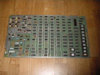 |
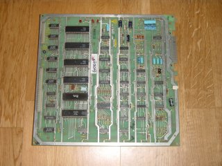
My main pcb (left pic.) and auxiliary circuit board (right pic.) of which the main board still has a fault. Despite changing the reset switch, 12Mhz crystal and various ic.s the only fault that remains is that the vector graphics are still screwy. |
 |
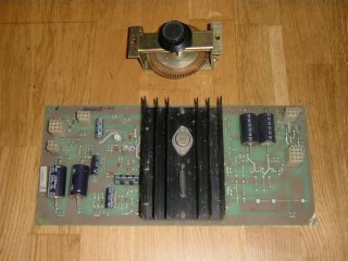 |
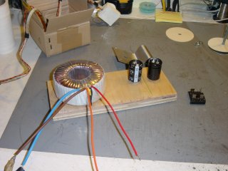
Left pic., the regulator pcb and spinner assembly. On the right the start of my build up of a substitute linear PSU using a torroidal transformer. (For the 36v AC) |
 |
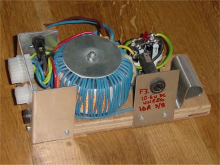 |
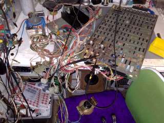
Left the
completed PSU, note the extra winding to supply the 10.6v DC (unreg.) On the right the PSU in action.......what a mess! |
 |
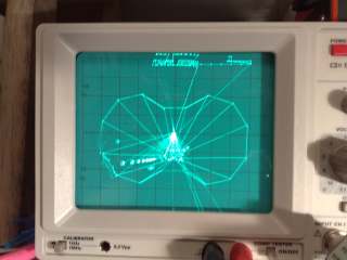 |
Left, I've connected the X and Y outputs of the main pcb to my scope (set up for XY display). Note the image is back to front and the retrace lines are visible. | |